
Visual Data Mapper Overview
Visual Data Mapper is used map data from one format to another. Using this robust visual tool, users can simply drag and drop to create maps which are used to convert source data into a desired target format, or use more advanced configuration options to set up complex transformations.
Step 1: Create the Map
Maps are accessed from workflow actions that use the map. If a map is not already assigned to an action, it can be created as outlined below. If the action is already configured, skip ahead to the next step.
To create a new map:
-
Open the workflow, and go to the Workflow Designer.
-
Create or edit the desired action that needs a map.
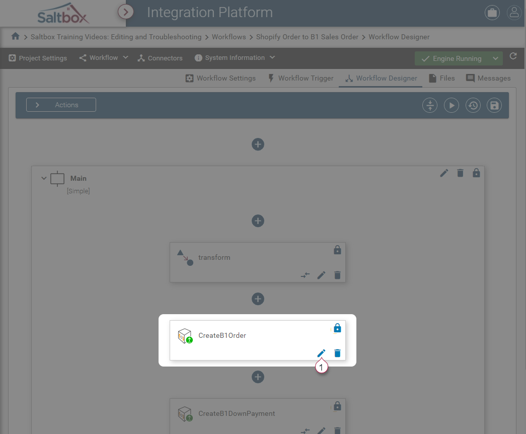
-
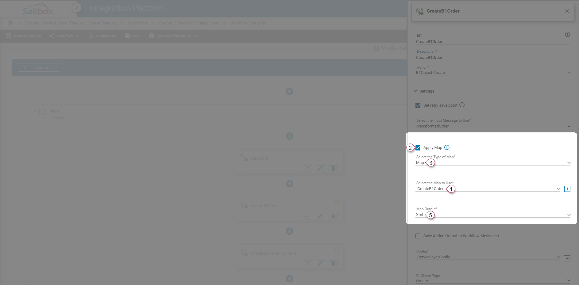
Enable “Apply Map” from the Edit Action pane and configure sub-options:
-
Set the “Type of Map” to “Map” in order to use Visual Data Mapper. Other supported map types may be selected which use file editors, which are not compatible with Visual Data Mapper.
-
Select the “Map to Use” or create one using the + button.
-
Set the “Map Output”. This can be used to format the output data so it can be easily uploaded by a connector.
-
-
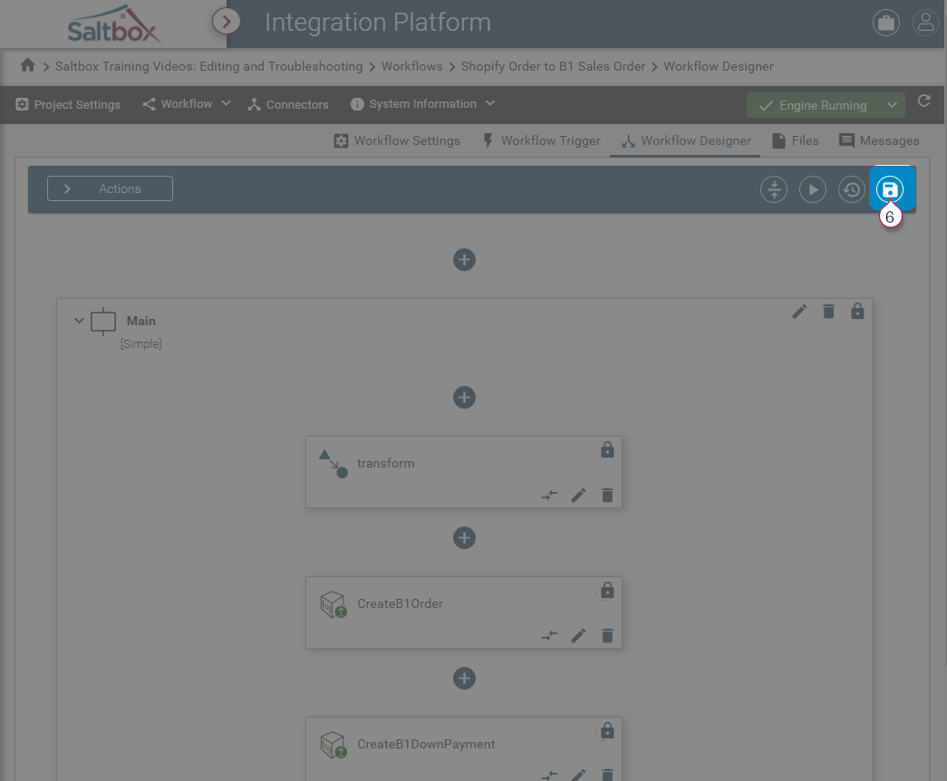
Save changes before opening the map.
Step 2: Open the Map
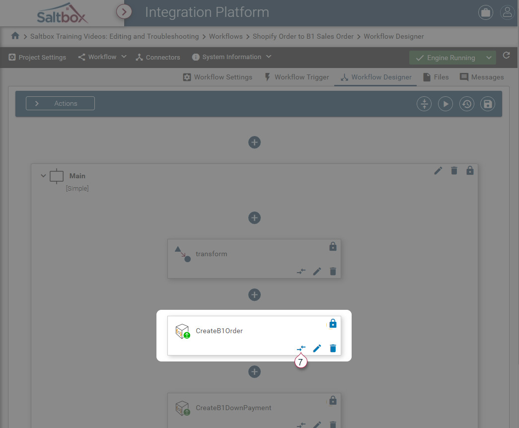
Visual Data Mapper must be opened from within Workflow Designer, and is associated with one or more actions.
On the Workflow Designer page, use the “View Map” button (marker 7 below) to open Visual Data Mapper.
Step 3: Load source and target samples
Visual Data Mapper uses file samples to define the data that will be mapped. Both Source and Target samples are required before mapping can be applied.
See Loading Data Samples for a walkthrough.
Step 4: Include parent nodes
Starting at the top-most root node, select each parent node that must be included in the target data.
Step 5: Select the Target field to be mapped
When using Visual Data Mapper, the goal is to format a target so that it is able to be used within the workflow. For example, the data may be uploaded directly by the action that used the map, or it may be processed for use by other actions within the workflow.
To ensure that only desired fields are mapped, each field on the target must be selected before it can be mapped to a source value.
If you can’t select a node, make sure its parent node is included in the map (as per step 4).
Step 6: Apply mapping settings
Select the desired Map Type from the Map Details pane.
Const- Constant mappings allow assigned values to be applied to the target. Alternatively, the + button may be used to map this to a variable (such as a project, trigger or workflow variable). No source values are used byConstMap Type.Direct- Direct mappings take a source value and map it directly into the target. Only one source value may be mapped usingDirectMap Type.Function- Function mappings allow Connector functions to define the target data. Source values, variables and constants may optionally be used byFunctionMap Type. For a complete walkthrough, see Applying Function Mappings.Calc- Calculated Field mappings provide a way to programmatically assign data to a field. Source values, variables and constants may optionally be used byCalcMap Type. For a complete walkthrough, see Applying Calculated Field Mappings.Lookup
Step 7: Update
Update the Target field settings before configuring any other fields. Failure to Update will result in changes being discarded.
Step 8: Save
Once target fields are configured and updated, they must be saved before the workflow can use the changes.
Press the Save button to save Visual Data Map changes.